Tuesday 15 December 2020

December 2020 Meeting


 Ho Ho Ho Santa's little surprise!...


Look closely, SER 0-6-0T's all round this Christmas.

What a year 2020 has been. We haven't met face-to-face for at least three quarters of the year but, like many others, we have maintained contact and discussion about our modeling projects thanks to Zoom.


Pete King: Above shows the station and yard area for Brixham. This has 4 turnouts and 1 catchpoint plus 2 inspection pits. As all of my crossings are full depth milled items, the first job was to flip each one upside down and mill 0.3mm off the bottom but leaving a small full depth pad around each fixing screw hole which leaves the crossing about the same depth as the rails and with a gap underneath (pic 2).


The following pics are just closer views. In the first of these you will see an Association wagon that I built ages ago but never painted. This wagon is so light that without the wheels in I’m sure it would levitate! I have run this up and down each road with the board on a slight incline and it showed up any irregularities by dancing off the rails. There is a little bit of tweaking still to do but it is nearly there. In the last pic the 2 pits are featured. These had to be made before laying the track over. I also cut through the sleepers before laying because I couldn’t think of a way of cutting through them in situ. This short section of track was the most troublesome of all because of trying to keep the rails to gauge as the glue was setting. Now for board 2.


I think it will be a little while before locos are running. Underneath that board is a forest of dropper wires as I’ve fixed 2 on each length of rail and 2 on each crossing. The light coloured half sleepers are brass sleepers for the droppers which are soldered into the hole underneath. By using liquid flux (I have always used paste before) It got through to the rail so the wire is soldered to the sleeper and the rail.


David Smith: No excuses this month I had to self isolate thanks to the NHS COVID app although I felt fine, with time off work and unable to leave the house I put time to good use building the remaining tank wagons from my stash as well as the attached photos (below) was taken at Tutbury to show the finished wagons, when nobody was looking the layout came over all 1970’s!) Also the shed/ workshop got a makeover with some old cupboards that replaced the open shelves. 


Tank wagons ready for the paint and weathering shop. A discussion followed about the merits of enamel and acrylic colours for airbrushing. David prefers enamel, finding acrylic sometimes difficult as it dries too fast clogging the airbrush. Also adhesion is poor and can peel or flake. Alan suggested using Etchweld an aerosol primer that makes a very strong adhesion for paint.


Richard Doust: PeteTownsend had mentioned some 2mm scale 3D printed kits of industrial line side buildings and vehicles, some buildings are motorised - www.dapr3d.com


Richard bought kit mainly to see how finely detailed they are; verdict - very good for scale.


Pete Townsend;
Trains are running on 'Leigham Road'. To see the movie of click on the link here.

Merry Christmas and a Very Happy New Year to all. Regards from KEAG
See you in 2021


Sunday 22 November 2020

November 2020 Meeting

Now  well into November and sometime past our actual scheduled Zoom meeting for the month, this comes with an apology from the editor for a late blog post. Despite the glimmer of light at the end of the proverbial tunnel, face-to-face meetings still seem some way off, and the exhibition calendar is pushed further away too, adding to our frustrations

With the current lock-down, we should, in theory, have time for more modelling, but sometimes with little to show. So here is our offering for November.


Alan Smith has been fitting in the continuation of preparing wagons for Evercreech Junction, and the demands for supplies for the 2mm Association shops and committee meetings.  

This  photograph shows 2 batches of various wagons all the chassis are complete less couplings and buffers.
The body's are now awaiting the paint shop.

It was found with earlier wagon builds that a little added weight improved coupling performance and track holding. For wagons I have 2 types of weight the smaller is relieved to clear the brake etch where it is attached to the floor. Relief in the 4 corners clears the wheels. the longer version is for my earlier wagons where I did not form the coupling mounts as I had used 3 link couplings.

Van body and unpainted chassis shows the weight fitted into the floor of the van body.


(below) 3 vans now almost complete with Cambridge Custom Transfers.
These were recommended by David I found them easy to apply and had a very thin transfer film.


As the vans above, these just need a sealing coat of varnish and a light weathering.

Tom Cutting had several questions for Alan regarding soldering flat bottomed track to a PCB base. The first was how to transcribe the Templot templates onto the PCB. The intention is that on this part of the layout the track will be recessed. Alan suggested contacting Keith G who has shown examples of this track construction for part of Evercreech Junction. (see October for an example). Also discussed was how to achieve electrical track separation, scribing the copper PCB surface was suggested as the preferable method. 

Pete Townsend sent two images of the progress on his 'Leigham Road' layout; Leigham Road station and work on the fiddle yard and traverser.


It now looks increasingly likely that all the booked exhibition appearances of Lightermans Yard have been cancelled or postponed until further notice.

Wednesday 21 October 2020

October 2020 meeting

Suspecting that to most 2mm modellers this time of forced separation has become somewhat wearisome. Being unable to discuss face-to-face the finer details of each others progress with models and the practicalities of personal and/or group projects. The use of social media such as Zoom has alleviated the separation to some extent as we become more familiar with our screen presence. We know that within our small group, there is some enthusiasm for keeping in touch, and some despite the current and drawn out crisis, others are not so keen.

Looking back at the blog entries since we last met in person, even our forty minute zoom sessions have been fruitful and kept up morale. We have been able to show each other the progress of on-going projects and gain from practical discussion. 

So down to this month's business!

Alan Smith. Once again I have been distracted away by other things 2mm. and have not progressed as much as I would like.

The black and white buildings are the limited progress on the water tower for Evercreech Junction. It looks like the brick work detail does not show up in the photos but it looks OK by eye. The corner 'quioinin', dodgy spelling, needs a chamfer on the inside edge to form a mitre so it lines up on the outside.


Here are a couple of shots of the steel bolsters I made to fit a commercial moulding machine.

The original bolster block with die plates fitted to inserts fitted to bolster. this was an attempt to standardise tooling into one set of bolster blocks. 


This shows the current problem. The die plates from "Cambrian" are larger and will not fit within the width of the bolster. The bolster has to fit this way round to fit the moulding machine.


Die plate has been cut down to fit bolster plate by roughly 6mm. 


This modification was done after checking all of the tooling. 3-4 tools cannot be cut down in this manner as the details within the die face fill the whole of the die face area.


Because we do not sell vast numbers of our wagon kits, I thought I would try to mould a few shots "in house" Once again I found that the new tools were too tall to fit my machine, after some head scratching I found that it was possible to add 4 spacers to the top of the machine raising the injection nozzle up by 20mm. This gave enough clearance to fit the die plates. (picture showing 4 extensions to the top of the press)

A quick lash up got me to a point where I could try out the system. After many trial shots I only managed to get one complete fill.

The plastic was solidifying before it fill the mould completely, I needed to heat the mould itself.


A piece of aluminium plate was found and drilled out to take a cartridge heater. The one I had was 120W
so some form of control was needed as I did not want it to run at full power. A rummage in the "it will come in useful one day" drawer came up with a 500w lighting dimmer. A quick bit of wiring to make it safe and the heater plate was complete.
 While I was at it I made a better back stop this allows the die plates  to be positioned under the nozzle repeatably. 


The heater plate is now installed and works as expected the issue now is that it takes a lot of pressure to inject the tool and the die faces are spreading apart causing "flash" Indeed I have screwed the plates together and still I get flash. I think I just need more clamping pressure so I am looking into how this can be done.


Howard Watkins. 3D printed and is from Osborns Models. Unlike the Langley white metal offering (difficult to drill), it should be easy to replace the steering wheel (a solid disc in this case) with an etched brass wheel.

Howard also opened a discussion on some useful additions to the work bench. The first item is Ceramic tipped tweezers really useful when soldering, Search here on ebay.

The second items were Garryflex abrasive blocks. These come in four grades, of which 240 grit (£6.50) is probably the most useful - cleaning metal surfaces for soldering etc. A source are PJS Industrial Supplies also on ebay


Tom Cutting. is working on the track for an entry to the Diamond Jubilee model celebration. As the track is mostly running in paving it was suggested that a way of dealing with the complex cross over and to avoid difficult sleeper arrangements, he should lay the track directly onto PCB. A technique below employed on part of Evercreech Junction by Keith and Alan.


Richard Doust. Somewhat out of scale and in an attempt to satisfy an over eager grandson(9), here with, apologies, is a bedroom '00' gauge layout as a stop-gap to a larger venture.

Pete Townsend. Progress in Somerset.....


Thursday 24 September 2020

September 2020 Meeting


It is now almost six months into what has become known as 'the new normal'. For us and many other 2mm groups, that has meant virtual online 'show and tell' mediated over forty minutes Zoom sessions, replacing our monthly four hour face-to-face meetings, variously lubricated by the comfort of mugs of tea and chocolate biscuits - and, of course, chat and the opportunity to actually run model trains.

That having been said it doesn't necessarily mean the 'zoomer's' amongst us do not enjoy the company of those who regularly appear in front of their computer screens. What we have to show and discuss, is almost as good as being there in person. Almost certainly we face a further six months of isolation before tentative re-assembly can resume.

One advantage is that the 2mm community has expanded as Zoom has allowed members to participate from distance, as could be seen and heard during the recent Zoom AGM, members from across Australia who were able to take part and several UK members have joined the local zoom Aussie/NZ meetings. There were even live online modelling demonstrations from area groups. This widening of the 2mm community is to be welcome and perhaps in itself become an addition to the normal.

This blog entry is the sixth since lock down, lets hope we can maintain our presence until we can report on meetings offline.

September and the AGM 

AGM Alan Smith reports; For those of you that couldn't get online for the AGM all business was passed with only a couple of questions from the floor, mainly regarding the 'Covid' situation and implications of association events.
I think around 54 members attended, so its up there with a normal AGM. Nice to see some faces from across the globe and to put faces to names that pop up everywhere. Although its nice to get to see everyone. its difficult to communicate one to one or as a whole group. Given the situation its probably the best we can do.

The AGM Model Competition for 2020 was run online, with online voting from members. Awards were announced at the online AGM. Category; 'Diesel and Electric Powered Locomotives, Railcars and  Multiple Units - Winner David Smith (KEAG) for Metrovick Co Bo. Congratulations David.


The British Rail Class 28 diesel locomotives, known variously as 'Metrovicks', 'Crossleys' or 'Co-Bos', were built under the Pilot Scheme for diesel locomotives as part of the British Railways 1955 Modernisation Plan. 

David Smith The class 25 (below) is a Bachmann model that has had a little work done on it mainly the fuel and water tanks between the bogies to get a bit more 3D feel to it, the main underframe has been moved inboard a mm or so to give more relief. Very little work has been done to the body apart from finer handrails and lampbrackets on the nose ends, the glazing has been thinned down on the rear by rubbing on finer and finer wet and dry paper Until it’s only a mm or so thick then polished to restore clarity hopefully it stops them looking like they are in  made from the bottoms of milk bottles all it needs is someone to do some fine etches for the radiator grills.


Alan Smith
First the servo mount. This is made from Perspex sheet I choose Perspex as you can see through it which helps when under a baseboard when trying to mount it. The base is made from 4 layers, the top layer locates the tie bar this is a beefy piece of double sided PCB with two 1mm brass tubes that the dropper wires from the point blades go into. This layer together with the second layer can be easily adjusted to locate onto the blade droppers to mounting holes can be spotted through and drilled for screws there is a slot at the front location to aid final adjustment, the two screws then hold this in position.


The body of the mount, layers 3 & 4, now screw to the already located layer 1 & 2 if a servo or switch gives up it can be easily changed. The servo and micro switch are mounted onto the top layer with more stainless screws. The servo horn drives a 0.8mm brass wire pin through the base of the mount and into a bushed hole central of the tie bar. A servo horn extension has a leaver that actuates the microswitch.
Perspex sheet has a few properties which are useful in making things of this kind. Apart from being clear it is quite rigid and is reasonably cheap. It machines well and can be glued using plumbers pipe solvent.
As you can see I have been busy and have produced around 50 of these units roughly half of that required for Evercreech Junction.


The above photos show a long term project I have been working on. For many years I have wanted a rigid milling machine, a lot of hobby machines are flimsy usually having a round vertical column on which the head rises and falls, this often leads to inaccuracies when setting the head. Once this is done it is prone to moving when taking heavier cuts or having a poor finish when doing fine cuts every job seems to have a compromise. I suppose I have been spoilt by working in industry where large tool room machines were chomping away all day, it seems, without any effort.
This machine came up so I decided to buy it. I knew is was a bit untidy but nothing that could not be fixed. Initial trials proved that indeed this machine could do all I could ever ask of it. It could both 'rip' off large cuts or do fine work. Moving the dials by 1mm or 0.1mm would take of just that, no more, no less. A workshop move around was planned to fit it all in but I thought I would tidy it up first before this. About 7 years ago I stripped down various bits and started to prepare for repainting. This was not to be a nut and bolt restoration as the machine did not need it, it was purely to clean it up. This then got delayed for one reason or another hence it has taken so long. Alas I now need the space for a railway, the workshop has grown another CNC machine, and the BIG UN cannot be fitted in. So its off to the great auction site in the sky, offers accepted.........

Pete King (for Evercreech Junction) I have, at last, finished the branch sidings turnouts. The tandem made me say “bother” a few times! If you look at it it’s quite an elongated affair and the problem was setting it out so that the various check rails and crossings didn’t get too close to one another.


Keith provided an image of the entrance to the yard


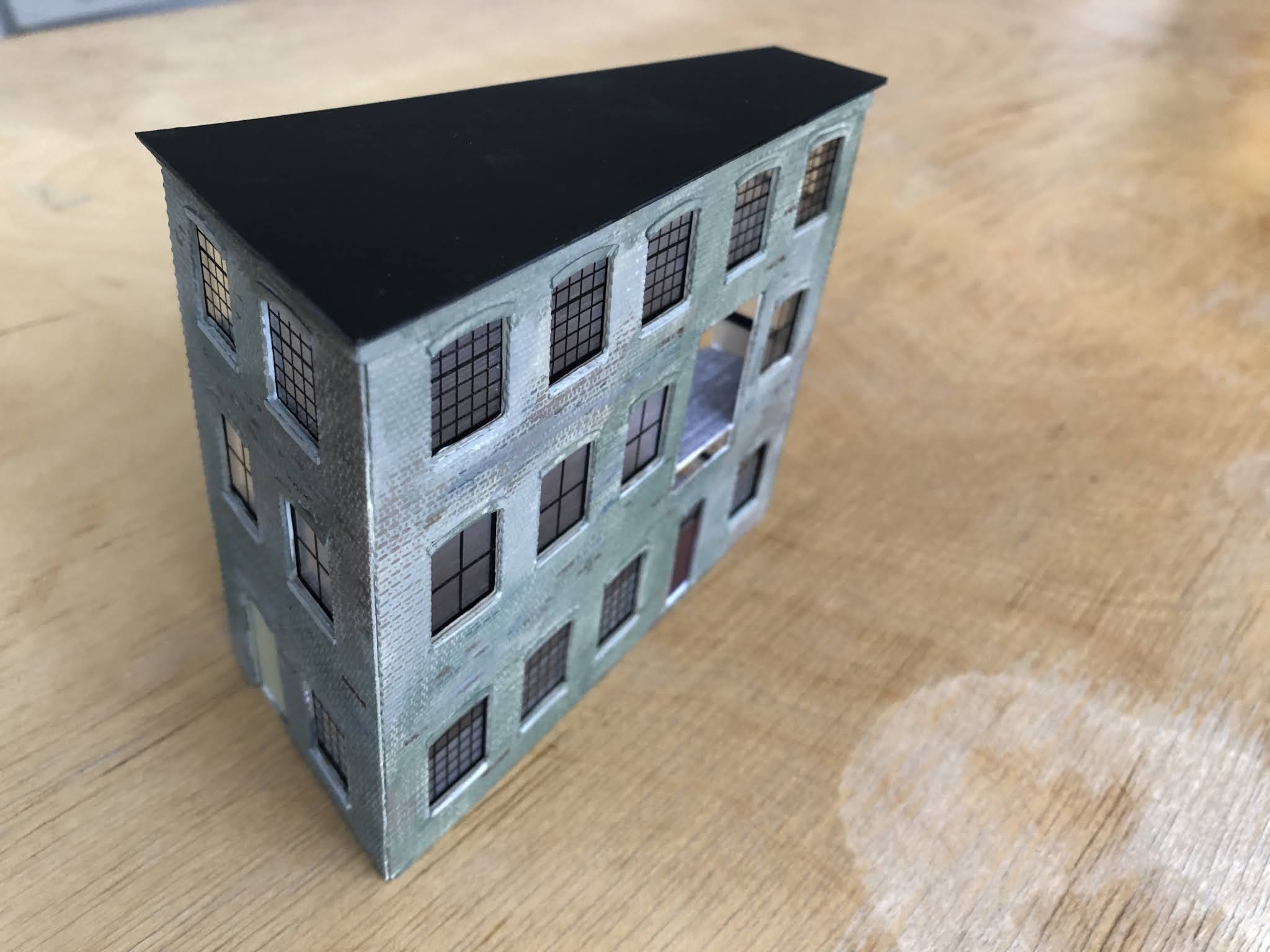
Richard Doust Progress on the shipyard is currently concentrating on the office and workshop buildings, finding out how the different methods of scratch building work - on not! The images are of the main office block - almost there!


Tuesday 25 August 2020

August 2020 Meeting

Apologies for the late posting of this month's report. It's well known in the press that August is the 'silly month' when there is no real news. Of course, that is until you come to August 2020 when we are suddenly saturated with news, most of which we would prefer was not news.  

We did meet as scheduled for a Zoom meeting on Sunday 9 August. However, we were a reduced cohort, so our news is somewhat short.

Alan Smith, in between supplying the 2mm shops, demonstrated progress on track laying for Evercreech Junction.   

The photos of the layout show the 'new' plan overlaid on the baseboards. The 'new plan' was necessary as the first was unfortunately under scale. Special thanks here to Peter King for all his efforts with this, not only doing the plan once but twice!
The files have been printed off and pasted together or rather taped using many reels of 'magic' tape.
This gave best fit to the boards making sure that turnouts did not occur at base board joints.  The plan then being tacked and trimmed to fit base board surrounds, the plan was cut at board intersections so the whole lot could be dismantled. Further copies of the plan can be printed off and used for track construction.
 

The south crossover has been made again this time I have used plain Easitrac chairs and sleeper strip. the crossings being fabricated from rail rather than being machined from solid. Comparison between the two systems shows that this is quicker than machining the base and crossing, or rather doing all the drawings that enable the parts to be machined. This system, as originally designed, is straightforward to use but for belt and braces I have added additional PCB sleepers and brass chairs at various points for power feeds and anchoring the rails.

 
It was found that the crossover in its new form had grown from B10 to B12 in size.
Keith has been busy finalising the fiddle yard track work with just a few more switch rails to add. Further progress has been made fabricating servo mounts which will be gobbled up at a great rate in the fiddle yard and elsewhere. Current servo count is just over a hundred.
Better get a big power supply..........
Richard Doust showed the continued work on an office building for his shipyard challenge cameo. Having given up on the scoring of brick work and particularly around window openings and including the arches over windows. The cutter just could not manage the required detail at 2mm scale. However, the window openings were fairly easily  cut from a vacuum formed styrene sheet of English Bond brickwork, the over arches being added from a thin plain styrene sheet. An inner match was cut from thicker plastic to strengthen the shape. The front of the building has a bay window above the office door (shown here but not yet in position).
The building taking shape, with thin over window brick arches and sills in place. Also the floors making the building rigid. The last image shows the rendering of industrial brick work (tiled roof to follow, and the bay window and detail yet to be attached). The tapered shape of the building tmerges into the background and allows for track clearance.  
 
And lastly this month, another view of Leigham Road, from Pete Townsend.