Monday, 26 April 2021

April 2021 Meeting


 At last out attention turns to the possibility of a 'real' meeting in the months ahead. A chance to closely inspect and handle, and discuss techniques and practical solutions.

The blog will still play it's part, as it did before restrictions, a running digest of our work around Lightermans Yard and individual projects.

Here is April's account;

Pete King; Brixham. I’m not exactly breaking any records here but the track is now laid on both the main station boards (below). On the lower right of the layout (as viewed in the photo) the track will carry on up a 1 in 78 incline for a short distance before diving through a hole in the sky. The incline starts just past the first turnout (lower right).

I have also been working on an adjustable mount for the crossing polarity micro-switches. Photo below shows the assembly with the centre screw locking the switch to the adjustable base. The other two screws pass through this base into the fixed base and hold the whole assembly together. By slackening these outside screws it allows the adjustable base to be rotated right and left via the radial slot. Photo 3 shows how it will look when fixed under the baseboards.


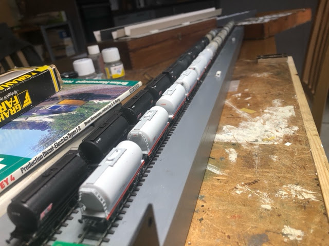
Alan Smith: Evercreech Junction. Progress has been slow as I have been tied up on other projects.
From last month the track through the station was laid but not fixed down. I needed to check for clearances against the platform edges. As there is a central track I had nowhere to go if things got tight.

After a couple of attempts at the platform I clad both facing edges with stone Plasticard, only to find that the up platform was indeed built from brick. The stone facing was duly stripped off and brick facia applied. I now have to fabricate the platform flag stones and line the edge. At least now I have a uniform curve with the platform edges from which I can lay in my track and know that locos and rolling stock will pass through.

The sidings and point work in the station yard have progressed a little I have now to fit the point blades and open out the tie bar areas on the underside of the boards to allow the servo arms to fit.


Because of the location of some of the points an extended arm
will be required, more of this next time.


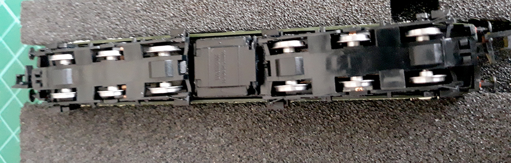
The other projects....
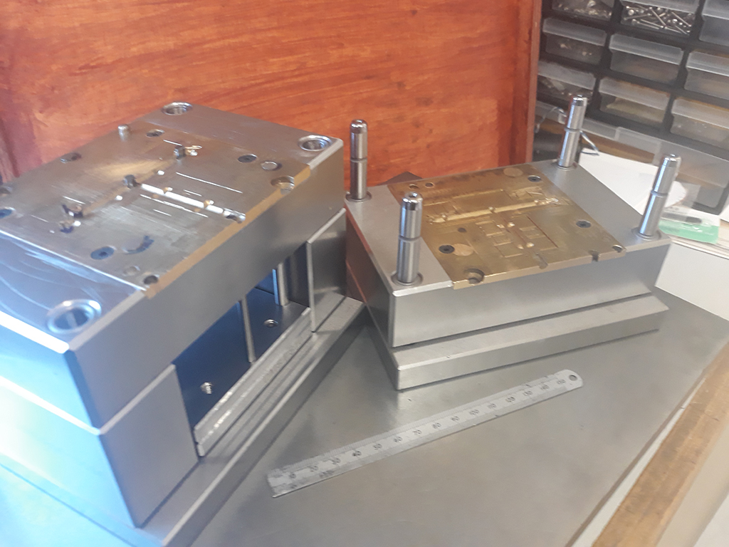
Are a die set for the association tools.
The main blocks for this are supplied precision ground all over and bored to fit the guide pins and bushes. The pins and bushes are a press fit into the blocks the rears of which locate further blocks behind. My main job was to machine a socked in each die plate to take the tool plates.
As received from the original moulder and maker of the plates only the front edge and rear edge were parallel to each other. The sides of the tool were just rough sawn and looked like they had been attacked by a hungry beaver! the sides were duly cleaned up to make the plates 95mm wide with the ingate in the centre. these then had to be fitted to the die plates and secured with screws. It was found that some of the proposed screw holes interfered with old existing tooling holes, these were duly plugged up and re machined flat so that the new screws could fit unhindered.
The next job was to fit the push pins and ejector pins. The location of these was already laid out in the tool plates so these were duly transferred into the main blocks 4mm pins for ejectors and 6mm for the push backs. A further 2 off 1.5mm pins were also duly transferred. Drilling through 38mm of steel plate with a 1.5 drill was achieved by multiple 'pecks' and lots of cutting oil. Not applying too much feed also assisted in keeping the bore straight. All the holes were then reamed to their correct diameters.

The pins themselves are precision ground and hardened and as supplied are about 50mm too long so would need cutting down. Before I could do this I had to drill and counterbore the pin plates.
Again these are precision ground and one plate needs to be drilled and counterbored to fit the heads of the pins. These pin plates are screwed together trapping the base of the pin between them to drive the pin assembly back and forth, so the counterbores need to be fairly accurate or the pins could become sloppy in their action.
I made a few small CNC programs which enabled me to centre up each hole in turn and counterbore for the pin bases. Once I had the pin plates completed the die set was assembled and I could determine the final length of the pins. As I mentioned earlier these pins are hardened and ground so I had to grind these to length. I dug out my home made cutter grinder and duly rigged up a contraption to assist the grinding of these pins. This set up enabled me to get the lengths fairly consistent we shall see if they need any adjustment when the tool is run,
Fingers crossed....

Richard Doust: Following on from the animated stills of Lightermans Yard for the Virtual RailEX. Ian Morgan has come to our rescue with some great video footage of the layout. I am currently incorporating this into our video.

Next meeting; Sunday 9 May at 13.00 online


Saturday, 27 March 2021

March 2021 Meeting

It's almost a year since we found ourselves in Covid lockdown and unable to meet face-to-face. At the time we probably didn't think we would be in the same place a year on. Enter Zoom and other Internet meeting software. Our meetings went online and provided a means of maintaining contact and keeping up to date with our projects.

One of the casualties of maintaining our distance is that the exhibitions and events that we would normally visit or take part in were suddenly canceled or postponed - all that planning etc...

Richard
Lightermans Yard was to have been exhibited at RAILEX this spring. Railex canceled the live exhibition and have invited would be exhibitors to contribute to their alternative web based show. Of course, although well photographed, just as you need video footage all you have are stills! Below is a link to what has been made so far, it needs some more work. There are a couple of corrections to make before we submit the animation
to Railex.
 

To watch the movie in your browser,    https://vimeo.com/522447128   password:  LIk51g

David


The wagon photo is a steel coil conversion of a standard bogie bolster D, this really just involves the addition of two wooden cradles over the bogies, these are made from various scraps of plastic strip rubbed over with course wet and dry paper to give the hint of wood grain, the coils are rolls of paper covered with painted squares of tracing paper to represent the tarpaulin the coils are wrapped in, not entirely happy with them so a bit more to think about the base kit is the usual Stephen Harris etch.
 

The next photo is a bit more of a long term project!


Howard

Here is a picture of me scanned by Modelu, and (below) 3 figures - 2mm, 4mm & garden railway scale. "I borrowed a railway cap and waistcoat but forgot to wear a tie!!!"


Alan

Photo 1 shows progress on board 2. This is the main station area and goods yard.
I found when laying track on board 1 there was a tendency to move as it was transfered from the building board to the layout. Copies of the plan were glued to the cork base and sleepers and track glued to this to eliminate the problem.


To check clearences of the 3 tracks through the station the platforms were fabricated from ply. The first attempt being cut on the band saw was not up to the job. The platform edge was anything but a smooth curve. Plotting from coordinates into CAD and cutting on CNC was much more successful.

The length of the platforms cut into 4 to fit the machine. Further experiment allowed the ramps at platform ends to be machined also.
Upon fixing stone sheet to platform faces it was noticed from studying photos that the platforms are indeed different in that one has a brick face with stone continuing about half way down the up platform. Some ammendments are to be made and once complete track laying can continue.


Pete Townsend

Most of my progress this last month has not been particularly visible. I have been tidying up the wiring, now that I know that it works correctly. 
One thing I have done is build and fit a couple of working semaphore signals. They are not up to the standard of some of the works of art that I have seen in the 2mm Magazine,  but they work well, servo powered, and look OK to my eyes. I can't show you a video of them working at the moment as I've got bits of the electrics disconnected to fit some sensors in the engine shed to stop me hitting the back wall with my locos.


Additional notes; Howard mentioned Posca pens for fine detailing, in this context - figures. They are available in "extra fine" with a 0.7mm tip. He bought his from Hobbycraft, (although currently out of stock).
They are currently on special offer here;


The Lifecolor acrylic paint sets are available from here and here; The most useful for us are "Dust and Rust", "Flesh Paint", "Weathered Wood", "Rail Weathering", "Shades of Black"
David mentioned Molotow pens with an even finer point.

Howard also showed a novel cut out and locomotive personalised birthday card


 Next meeting Sunday 11 April 2021 13.00


Wednesday, 17 February 2021

February 2021 Meeting

It is now ten months that we have had to present ourselves as virtual beings! All too soon it will be a full year and still doubtful that we will be able to meet in person. At least our 'lockdown' Zoom meetings have allowed us to keep in touch, and have even shown some modelling advances during this period! 

2020-21 would to have seen Lightermans Yard at a number of exhibitions and shows. We tend to be rather happy when we have the layout running for the public and overhear visitor's and other exhibitors, generally enthusiastic, comments. It will be good to get back on the circuit.


Alan Smith; Clas31


This is the new release model from Farish it has been updated to take sound and there are sound fitted versions available. It was bought to our attention that the 2SA replacement wheelsets did not fit.

Upon inspection it was found the Farish have changed the gears on the driven axles. the originals being 16T and the new ones 14T. Unfortunately 14T axles were not available from the shop so I got together the necessary parts from our in house manufacturers and assembled some. This proved to work out OK and the loco now runs as quietly and smoothly as original.

If anybody needs to do this re wheeling exercise the parts, ie complete axle sets will be available from shop 3 shortly.


The photos of Evercreach Junction (below) show progress with boards 1 and 2. Keith and I decided to make the crossover with fabricated crossings, this meant I needed to introduce some PCB sleepers in the formation to allow for electrical connections. this is also useful for anchoring the rails longitudinally. A lot was learned from this approach and on the next board I shall be building directly over the plan which will be glued down onto the cork subbase. This will save the issue of parts moving in the transfer between build board and layout. Brass sleeper sections have been used at board joints these are soldered directly to both 12BA and 8BA brass screws tapped directly into the ply baseboard deck. This makes for a really secure fixing at track ends the rail also being soldered to the chairs. The 8BA screws go all the way through the boards enabling electrical feeds to be secured to them.


Pete Townsend; More from Leigham Road

Richard Doust; Minor developments on the shipyard project, buildings and background.


Thursday, 21 January 2021

January 2021 Meeting

Like most small publishing enterprises, specialized editorial content for magazines and blogs are always going to be a challenge. Witness pleas from the editors of the 2mm Association magazine for members' contributions. Even renown publications like the MRJ seems to struggle.

This is an observation not intended to be over critical of our own very limited group membership, the blog has been an important addition to our monthly face-to-face meetings. Even though we have been forced away and relying on Zoom to share our various projects, the blog report has acted as a worthy endeavour virtually keeping us together.

Maybe the addition of a regular feature; maybe an image and a small amount of text, describing an interesting discovery; a problem solved; advice, rather like pre-Covid meetings; rather like our 'loco of the month' we featured.

In addition to the meeting report for the new year, included are some photographs discovered in a file detailing the start of work on Lightermans Yard.

But first the January's report; 

David Smith, Work has continued on the tank wagon fleet just need weathering and a bit of detail painting to finish,applying transfers was a bit of an ordeal with each wagon taking about thirty individual transfers the numbers were made up of individual digits with each number repeated three or four times per wagon with twenty six wagons done that’s about 750 transfers in total!


The resized class 37 continues with work started on the roof and nose end details, really should start on planning the chassis now the body is looking passable.

Pete Townsend. Adding circuit breakers to Leigham Road. Who said DCC is just 2 wires? They are made by DCC Specialities, a US company, they normally cost about $40 each. The circuit breakers trip very quickly and reset automatically.They save the whole layout stopping if there is a short anywhere,


Lightermans Yard, the beginnings in 1998


Tuesday, 15 December 2020

December 2020 Meeting


 Ho Ho Ho Santa's little surprise!...


Look closely, SER 0-6-0T's all round this Christmas.

What a year 2020 has been. We haven't met face-to-face for at least three quarters of the year but, like many others, we have maintained contact and discussion about our modeling projects thanks to Zoom.


Pete King: Above shows the station and yard area for Brixham. This has 4 turnouts and 1 catchpoint plus 2 inspection pits. As all of my crossings are full depth milled items, the first job was to flip each one upside down and mill 0.3mm off the bottom but leaving a small full depth pad around each fixing screw hole which leaves the crossing about the same depth as the rails and with a gap underneath (pic 2).


The following pics are just closer views. In the first of these you will see an Association wagon that I built ages ago but never painted. This wagon is so light that without the wheels in I’m sure it would levitate! I have run this up and down each road with the board on a slight incline and it showed up any irregularities by dancing off the rails. There is a little bit of tweaking still to do but it is nearly there. In the last pic the 2 pits are featured. These had to be made before laying the track over. I also cut through the sleepers before laying because I couldn’t think of a way of cutting through them in situ. This short section of track was the most troublesome of all because of trying to keep the rails to gauge as the glue was setting. Now for board 2.


I think it will be a little while before locos are running. Underneath that board is a forest of dropper wires as I’ve fixed 2 on each length of rail and 2 on each crossing. The light coloured half sleepers are brass sleepers for the droppers which are soldered into the hole underneath. By using liquid flux (I have always used paste before) It got through to the rail so the wire is soldered to the sleeper and the rail.


David Smith: No excuses this month I had to self isolate thanks to the NHS COVID app although I felt fine, with time off work and unable to leave the house I put time to good use building the remaining tank wagons from my stash as well as the attached photos (below) was taken at Tutbury to show the finished wagons, when nobody was looking the layout came over all 1970’s!) Also the shed/ workshop got a makeover with some old cupboards that replaced the open shelves. 


Tank wagons ready for the paint and weathering shop. A discussion followed about the merits of enamel and acrylic colours for airbrushing. David prefers enamel, finding acrylic sometimes difficult as it dries too fast clogging the airbrush. Also adhesion is poor and can peel or flake. Alan suggested using Etchweld an aerosol primer that makes a very strong adhesion for paint.


Richard Doust: PeteTownsend had mentioned some 2mm scale 3D printed kits of industrial line side buildings and vehicles, some buildings are motorised - www.dapr3d.com


Richard bought kit mainly to see how finely detailed they are; verdict - very good for scale.


Pete Townsend;
Trains are running on 'Leigham Road'. To see the movie of click on the link here.

Merry Christmas and a Very Happy New Year to all. Regards from KEAG
See you in 2021


Sunday, 22 November 2020

November 2020 Meeting

Now  well into November and sometime past our actual scheduled Zoom meeting for the month, this comes with an apology from the editor for a late blog post. Despite the glimmer of light at the end of the proverbial tunnel, face-to-face meetings still seem some way off, and the exhibition calendar is pushed further away too, adding to our frustrations

With the current lock-down, we should, in theory, have time for more modelling, but sometimes with little to show. So here is our offering for November.


Alan Smith has been fitting in the continuation of preparing wagons for Evercreech Junction, and the demands for supplies for the 2mm Association shops and committee meetings.  

This  photograph shows 2 batches of various wagons all the chassis are complete less couplings and buffers.
The body's are now awaiting the paint shop.

It was found with earlier wagon builds that a little added weight improved coupling performance and track holding. For wagons I have 2 types of weight the smaller is relieved to clear the brake etch where it is attached to the floor. Relief in the 4 corners clears the wheels. the longer version is for my earlier wagons where I did not form the coupling mounts as I had used 3 link couplings.

Van body and unpainted chassis shows the weight fitted into the floor of the van body.


(below) 3 vans now almost complete with Cambridge Custom Transfers.
These were recommended by David I found them easy to apply and had a very thin transfer film.


As the vans above, these just need a sealing coat of varnish and a light weathering.

Tom Cutting had several questions for Alan regarding soldering flat bottomed track to a PCB base. The first was how to transcribe the Templot templates onto the PCB. The intention is that on this part of the layout the track will be recessed. Alan suggested contacting Keith G who has shown examples of this track construction for part of Evercreech Junction. (see October for an example). Also discussed was how to achieve electrical track separation, scribing the copper PCB surface was suggested as the preferable method. 

Pete Townsend sent two images of the progress on his 'Leigham Road' layout; Leigham Road station and work on the fiddle yard and traverser.


It now looks increasingly likely that all the booked exhibition appearances of Lightermans Yard have been cancelled or postponed until further notice.